Information on how to build a VU-Sette.
Read more about the “VU-Sette” here: http://blog.worldofjani.com/?p=1127
The following articles/documentation have been used as information for this project:
64er 1985/10 p.xx (http://www.64er-online.de/download/1985/index.html)
Svenska Hemdator Nytt 1990-05 p.34 (http://www.selda.se/sub/hemdatornytt/1990_05/)
C2N/1530/1531 Service Manual Preliminary 314002-002 (1984 Oct).
The VU-Meter

The VU-Meter was pulled out from a “Precision Batterychecker mini” from ebay 😉
Prototype

An azimuth tape and Winter Games original was used for inspecting the signal.

…and more testing.
Circuit diagram for the VU-Sette.

I made a sketch with the information i had gathered. Connection points for “green” and “purple” can be found at the bottom of this page.
Component list:
IC1: LF356
R1 : 10 KOhm
C1 : 470uF
R2 : 62 Ohm 0,5W
Q1 : 2N3904
Speaker: 8 Ohm 0,5W
You might need to adjust the values to match the make and model of your VU-Meter/speaker. The speaker and the VU-Meter are independent of eachother. Either one can be left out if wanted.
Potentiometer R1 is for zero-adjusting the VU-Meter. The tape read-head signal and R1 must be adjusted to match. When the signal peaks, you want the VU-Meter be at the max position. You can use an original game, or a tape recorded with correct adjustment, to find the peak. Note that not all originals have a “good” recording signal to prevent duplicating.
The initial adjustment can be a bit tricky, but when it is done, you will only need to adjust the tape read-head when loading a tape.
I can think of some cases where you want to adjust the sensitivity further; for very bad/old tapes, or that the reference tape had a signal that was “too good” and you need to bring the level down a bit.

A Veroboard was used for the first build. I also needed to know much room there is inside the datasette for the pcb and VU-Meter. This version does not have the speaker.
PCB Layout

I ordered a few PCBs to test the concept. In retrospect, I would rather use solderpads for the speaker and for the VU-Meter. The VU-Meter would probably be able to hold the weight of the PCB and wouldn’t need any further mounting. The extra potentiometer snuck into the upper left corner can probably be left out, I wasn’t sure if there was a need for extra adjustment of the VU-Meter.
Assembly

A 22 mm hole for the VU-Meter was drilled 6 mm inwards from the junction.

Parts for the VU-Meter. The rightmost VU-Meter is from another batterytester i found on ebay. Both work with the VU-Sette, but the leftmost is easier to fit into the datasette.

VU-Meter with everything cluttered into the bottom left corner. 🙂

Fully assembled.
Finding the signal
The read-signal is amplified and filtered four times before leaving the datasette. Therefor the signal strength will be different depending on which stage you choose to tap the signal from. VU-Sette has been successfully implemented with the PCBs and connection points below. You might need to do some testing to find out which output stage is most suitable for your equipment. YMMW.
Datasette with one OP.Amp (PCB: 1530, 1531, NP-136H):

 1530 |
 1531 |
 NP-136H |
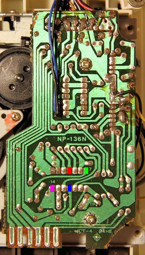
Datasette with one OP.Amp (PCB: CMR-001):
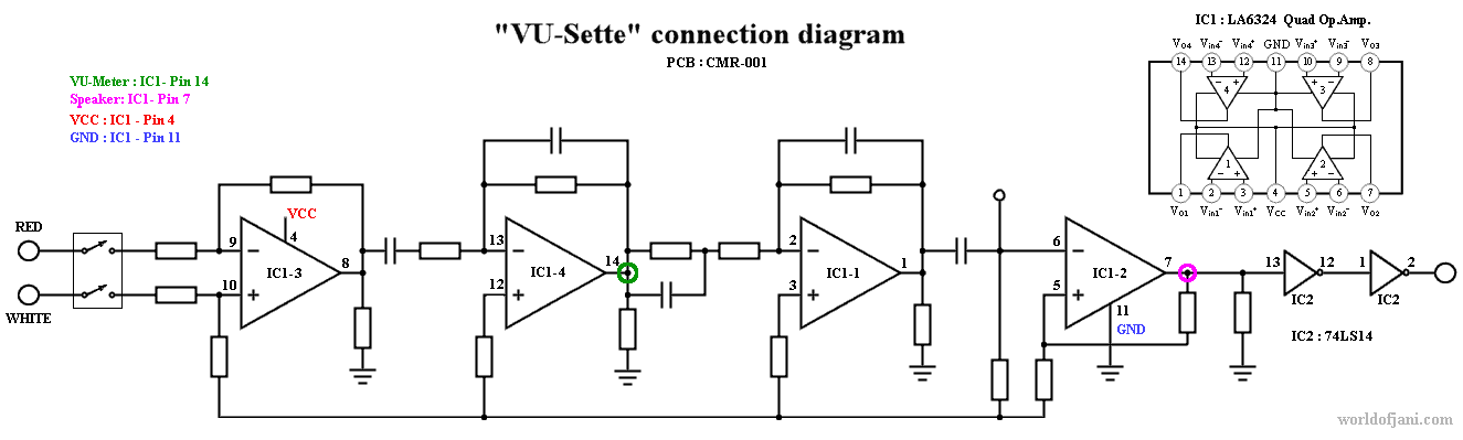
 CMR-001 |
Datasette with two OP.Amps (PCB NP-090B):

 NP-090B |


Comments