I got a bunch of disks for transferring. As a routine I do an ocular inspection and make sure the disks rotate before starting the transfer. The only problem was that these disks failed on both parts.
The disks came from a storage unit that had a water leak and the disks were soaked with a mix of water and concrete dust.
Stains of concrete dust. Trying to rotate the disks by hand made a grinding noise. Nothing you’d put in a drive.
The disks were warped since the cushion inside the jacket had gotten wet. No wonder these disks didn’t rotate.
I needed a new disk jacket and to be able to clean up the disks before i could start reading the contents. The disk jacket I got from a donor disk. I used antimagnetic scissors to cut open the disk jackets, both the donor and the disks that I wanted to preserve. The magnetic disk can be moved slightly off-center to gain more space at the top so it won’t be damaged while cutting open the jacket.
When removing the disk, do not touch the magnetic surface. A good tip is to wash your hands with dish-washing liquid to remove grease from your fingers before starting. The disk can be slid out without needing to touch the magnetic surface. You can give the magnetic disk a push by the center hub ring or by the outer edge.
When the magnetic disk is out, use your thumb and pointer finger to hold the disk by the center hub ring and the outer edge. Alternatively put a couple of fingers through the center hub ring. Again, avoid touching the magnetic surface.
I had the disk under running water to rinse the dust off. With a few drops of dish-washing liquid on the fingers of my other hand, I carefully cleaned the surface. I started from the center hole and moved straight out to the outer edge.
Let the disk air dry. Dry wiping is likely to damage the surface. On some stains (or mold!) I used 90% isopropyl alcohol with clean cotton.
After the disk had dried, it was inserted into the donor jacket and I was able to get a good read of the disk.
Spectacular Copy Turbo to Disk, SCT2D, has become a widely used tool for preserving turbo tapes. It was originally part of the “Spectacular Copy” suite by Stephan Senz. “Turbo to disk” was extracted and has undergone many improvements on the way.
Latest addon to the tool is a Fast I/O save routine for 1541-family drives.
SDT2D Changelog:
 v1.2 by SAILOR of TRIAD

 * Fastsave I/O for 1541 drives.
v1.1 by WACKEE of ARISE:
* Automatic replacing of invalid chars (,*?) before save [option].
* Accurate block size calculation.
* Proper handling of 0-byte files.
* Fixed resave on diskerror.
* Rename without space-fill.
* Tapeload with sound.
* Changed default settings.
v1.0 by SAILOR of TRIAD:
* Asks for disk change if file is larger than free blocks on disk.
* Resave option on diskerror.
* Option to rename file.
* Can use other devices than #8.
* Autotransfer mode option.
* Load error detection.
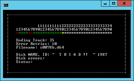
I needed a program to transfer C64 disks to .d64 images with a good overview of the process, but more importantly, it had to be fast and with minimial interaction to be used for reading disks in large batches. I ended up making a modified version of Nibread which i decided to call d2d64 so it would not be mixed up with the original Nibread. Nibread is part of the Nibtools utilities by Pete Rittwage at the C64 Preservation Project (http://c64preservation.com/).
d2d64 should not be used for preserving originals, it is only for making backups of your unprotected disks.
d2d64 has a new UI with a progressbar and colors to indicate status. It saves the disk as a .d64, defaults to 35 tracks, uses errorinfo if appliciable and will not reset/bump between reads. It also has an option for creating filenames based on the A/B-side of a disk. All you need to do is press Enter between the disksides.
I made a video on youtube that shows the process of transferring a disk. The whole video is 41 seconds, including initializing drive, turning disk and reading two disksides. Reading one diskside takes about 15-18 seconds. Hardware is a 1571 with serial cable (-s: SRQ) and a Zoomfloppy. OS is Windows 10.
There are two versions of d2d64 available. First one is based on nibtools (with SRQ support) for xum1541/Zoomfloppy users. This is probably the one you want. The second one is an older version based on mnib(predecessor to nibtools) and should be used with XMP/XAP1541 cables(LPT-connected drives). You can scroll down to the “Short history” part of this post for a brief explanation on the hardware differences. The older version I made between 2007-2010 when Zoomfloppy was not available. I decided to include it here in case some of you (like me) still have their XA/XM1541 systems running.
Short history
The Commodore drives communicate with serial communication through a DIN-6 plug cable between the drive and computer. For faster speeds, a parallel cable evolved allowing 8-bits to travel in parallel. The drive parallelcable was not a previous standard, but a cable soldered directly to the second VIA-chip on the drive and then connected to the C64 Userport.
The 15×1 drives don’t have a standard communication port and therefor you need a special cable to hook the drive to a PC. Early software even transferred files and images through the V.24/RS232-serial protocol.
Later on(1992-) came the X1541-cables which provided multiple options to connect your drive to the PC. The drive was connected to the PC through the LPT-parallelport which required exact timing to work. There were incompatibilities with some motherboards which were circumvented by different versions of the 1541-cable. The drive parallelcable was also available for the X1541 cables and added a “P” to the name.
Even later came OpenCBM, based on CBM4Linux, making it possible to communicate with drives under Windows NT/2K/XP with XA/XM1541 cables.
You can read everything about the X1541-cables at Joe Forsters homepage: here
My x1541 breakout box from the early days. This connected to the LPT-parallelport on a PC and disk transfering was done in DOS. Old PC-hardware did not work properly with all x1541-cables so i needed a device for testing combinations and different low level components.
XMP1541 in the making…
USB to the rescue
The LPT-Parallelport became more and more obsolete when the PC hardware evolved. Lots of tinkering with timings and settings was also required to get it working.
Till Harbaum worked on an USB adapter called xu1541 until he lost interest in 2007. Nate Lawson, with Wolfgang Moser and Spiro Trikaliotis, continued the project and developed it even further. In early 2009 the xum1541(pronounced “zoom”) was introduced, a full speed USB device with support for parallel transfers. Best known xum1541 implementation is the Zoomfloppy. Today OpenCBM also supports the xum1541.
A collection of disk covers that I have acquired during the years, also known as “Cover Art”. Use arrow keys or mouse scrollwheel to navigate though the covers and press enter or klick on the picture for a larger version.
Most of these covers are photocopies and some of them have had a rough life in the snailmail process. Addresses have been removed due to privacy reasons.
A friend of mine, Hedning/Genesis Project, sent me pictures of a 1541-clone that neither of us recognized and we asked around if anyone knew the name of the drive. Moloch contacted us with pictures and said it is known in the US by the name “Commander II”. It might been stripped of the labels when imported to Euro-Land and sold as a different product. The Commander II was reviewed in Ahoy issue 16, 1985 (pages. 28-38).
Update:
2020-10: Added scan of the manual, thanks to Steve Stroebel !
2016-07: Hedning was generous and gave me one of his drives, thanks a lot! I added a few more pictures of the drive.
2016-04: Thanks to Moloch we now have a name for this previously unknown clone. It was sold in the US by the name “Commander II”.
The LEDs might been replaced with green/red since some traces were broken. I also removed a home-made deviceswitch due to its bad construction.
The +5V is connected to the large area on this side of the PCB.
The mech is a Chinon F-051.
+5V/+12V PSU.
Pictures by Hedning
Serialports are located on the side of the drive.
“Diskett” was a local Commodore computer shop/service center located in Malmö, southern sweden.
The second drive, with serial 841633, does not have this sticker.
Remove the screws marked with red and lift the cover.
You need to loosen 4 screws to remove the shielding and additional 3 screws to release the PCB.
Detach the white connectors and lift the main PCB. There is a ribbon cable beneath the PCB which also needs to be detached. The back plate can now be removed.
Remove the 3 screws marked in the picture. There are spacers below that PCB which you need to take care of.
Spacers marked with red.
Two voltage regulators(7805/7812) are fastened to the black heatsink to the right.
Flip the drive around and remove the 4 screws.
The drive mech is now loose, lift the plastic casing.
I have repaired a fair amount of drives, and every time I find myself loading a test or a diagnostic software from disk. This is a bit of a contradiction since the drive being tested, or repaired, might not even be able to load a program. I also have a variety of tools for different purposes and wanted to have everything in one place.
This is why i created a 1541 Diagnostic Cartridge.
The challenge was to get all these tools to fit into a 8K cart. I wanted to keep the hardware simple and a 16K cart would have overwritten the Basic interpreter.
Therefor I have optimized both code and visual on the tools to keep the size down. Some tools are old, others were written from scratch and a few I rewrote in machine code instead of basic. A couple of the tools are still in Basic, but optimized.
The cartridge is an 8K ROM at $8000-$9FFF
You can also use RESTORE to return to the menu.
You may need to send a “I0:” or turn the drive off/on before running further tests if an previous error has occurred.
Alignment
Occasionally I get questions about alignment and aligning the drive. There are some differences of opinion how to align a diskdrive, my personal view, and how I do it, is to use a special analogue disk and a dual trace oscilloscope. The analogue disk is a factory produced disk and has patterns written on specific tracks. An analogue alignment disk can not be duplicated.
1541 Diagnostic Cartridge Alignment Check. This program was distributed with a computer magazine and gives a quick drive alignment health instead of hooking up an oscilloscope. The program was completely disassembled, compacted (code and texts) and disk routines rewritten to share I/O routines just to fit onto the cart with the other tools.
The Alignment check program can (I, however, do not recommend doing it this way) be used to adjust the alignment but it will only be as accurate as the drive, or system, the disk was written with.
The two first columns should be identical, otherwise the alignment is off by a whole track(or more), most often this indicates an incorrectly positioned head stop. The third column indicates how well the drive can read data off each track, its alignment, and should be 100%, or atleast very close to. Fourth column is between tracks (or half tracks), this value can fluctuate a bit even on a well aligned drive. The 1541 allows for some tolerance and therefore some values can be within reasonable limits.
It is very seldom when you actually need to align a drive for proper functionality. If the drive works in daily usage and does not make noise or do continious re-reads or searches it is probably ok. If a drive fails to read disks, begin with cleaning the head and lubricate the rails. If this does not help, the R/W head might be damaged, quite often seen on the Mitsumi D500 mechanism. You can verify it by measuring the R/W head using an ohm-meter. Remember that a slightly misaligned drive is probably able to format and read its own formatted disk.
Most important, if it works, don’t fix it 😉
Recommended reading : Commodore Diskette Diagnostic Manual Version 2 (3140451-01) and Commodore 1541 Troubleshooting & Repair Guide (SAMS)
Update 2020.09: C64iSTANBUL designed a PCB, You can find it on pcbway 🙂 Update 2019.12: A few words about alignment. Update 2019.12: TFW8B is selling their version of the cartridge. Update 2017.09: The Cartridge is also available at the Protovision shop. Update 2015.12: Upon request from their customers, The Shareware PLUS Commodore 64 & 128 Blog asked me if they could offer the 1541 diagnostic cartridge in their product sortiment.
1541 Diagnostic PCB by C64iSTANBUL. Looking great, thanks ! 🙂
I had a broken 1571 on which I located the problem to the powersupply.
The PSU is relatively easy to refurbish with new caps and so forth, but I wanted to try out a switching powersupply i had.
The new powersupply is a MeanWell PT-65A and is rated 5VDC/7A and 12VDC/3,2A. It also has a -5VDC/0.7A output which was not used. This specific model was on a €4 sale at a electronics distributor and the current ratings were good, hence the selection.
WARNING! LETHAL VOLTAGES ARE PRESENT ON THE POWERSUPPLY.
1571 with original powersupply.
Mounting plate.
Testmount.
A very tight fit, I had to make a cut on the left side.
The PCB is mounted on spacers and the cables were crimped.
This post spawned out of a discussion at a facebook group about the commodore diagnostics reporting errors when using custom kernals. I decided to modify the kernal detection routine to identify good known kernals from a checksum table. Thanks to Jonny Hylander, Fredric QJ Blåholtz and Krister Andersson for ideas and suggestions.
586220+ : Initial version. Disassembly and kernel identification routines by www.worldofjani.com.
586220+ v0.4 : Marty/Radwar sent a huge list of kernal checksums. This version is able to identify a staggering 49 different kernals, for example Professional Dos, RapiDos, DolphinDos and Speeddos. Download the v0.4 sourcecode for a full list.
586220++ v0.5 SX-64 Tape Port check removal : KiWi at www.SX-64.de sent me a version which works correctly on the SX-64. Scroll down for the download and sourcecode. See his page here.
586220++ v0.5 Expanded window for paddle test by Sven Arke. Klick here.
586220* Proper chip number display for SX-64 and C-64 by Ted Saari. Readme.
2020-06 : giox sent me an updated standalone program which identifies 137 kernals. There is an ID clash (which can be expected at some point) for 901246-01(4064 Kernal) and Armageddon.
The diagnostic 586220 does a checksum on the kernal ROM to verify if it is ok. It will only identify the original CBM ROMs. All other (even good, for example JiffyDos) kernals will be marked as “BAD”.
The 586220 was used since i have done an reassembly/disassembly of it earlier.
1
2
3
4
5
6
7
8
9
10
11
12
13
14
15
16
17
18
19
20
21
22
23
$892f
;KERNAL ROM TEST
LDA#$37
STA A01
LDA#>$E000
STA AF9
LDA#$20 ;$2000 bytes of memory (20 pages)
STA A0F
LDA#$00 ;set checksum = 0
STA AF8
TAY
CLC
I8941 ADC(PF8),Y;+
INY
BNE I8941
INC AF9
DEC A0F;page counter
BNE I8941
ADC#$00
;<A-register holds checksum
Code to calculate the checksum.
Depending on $FF80(Kernel revision) the checksum is either $E0 or $E1. This determines if Kernal is marked as “OK” or “BAD” by the diagnostic test.
I remembered that the C128 diagnostic cart displays the checksum. When running the C128 diagnostic(789010) the checksum on the C64 Kernal is reported as $D4. After investigating the code, which is identical to the one above except for the fact that only $1F00 of memory is checked, this is probably due to $FF00-$FF04 belong to the MMU.
We shared ideas about how this would be accomplished, but also noticed that some of the different kernals generated the same checksum. This might be deliberate for them to pass a diagnostic test.
All code below is compatible with 64tass (i.e. Turbo Assembler compatible).
1
2
3
4
5
6
7
8
9
10
11
12
13
14
15
16
17
18
19
20
21
22
23
24
lda#0
sta zp_chk1;csum1 lo
sta zp_chk2;csum2 mid
sta zp_chk3;csum3 hi
sta zp_addr+0;addr lo
tay;=0
chkloop clc
adc(zp_addr),y;+
bcc chkskip
inc zp_chk2;csum2 mid
bne chkskip
pha
tya;addr lo(y)
eor zp_chk3;csum3 hi
sta zp_chk3
pla
chkskip iny
bne chkloop
inc zp_addr+1;addr hi
dex;pages tocheck
bne chkloop
sta zp_chk1;
The new checksum routine. To make a distinction, the address lowbyte is xor:ed and therefor not resulting in an identical checksum.
…I made a program that can identify the kernal ROM.
1
2
3
4
5
6
7
8
9
10
11
12
13
14
15
16
checksumtbl
.wordrom_name_1
.byte$bb,$d4,$fd;checksum901227-01
.wordrom_name_2
.byte$b6,$c7,$0a;checksum901227-03
.wordrom_name_3
.byte$bd,$c7,$0b;checksum sx.251104-04
rom_name_1.text"901227-01",0
rom_name_2.text"901227-03",0
rom_name_3.text"251104-04 sx64",0
A table is used for the checksum and a pointer(.word) to the matching ROM name. You can easily add new checksums and ROMs to the code.
Incorporate the checksum with Diagnostic 586220
The goal is to replace the original checksum routine with the code above.
1
2
3
4
5
I822C JSR I8888;COLOR RAM test
JSR I890E;KERNAL/BASIC/CHARAC ROM test
JSR I8A44;CASSETTE test
As we can see in the disassembly, the routine for ROM tests are at $890E. Further investigations reveal that code between $890E and $8A44 can be replaced. This area also has the routines to check BASIC and CHARACTER ROM.
Checksum routine is located a few lines below $8926.
After inserting the code, you can now assemble(compile) the code with c64tass. I won’t go into details about the code itself, but it is presented and downloadable further down on the page.
1
2
3
64tass-a586220plus.tas-o586220plus.o64
The output file (.o64) can now be written to an eprom. Skip the two first bytes (0x00, 0x80) which is the loadingadress of the file.
The following articles/documentation have been used as information for this project:
64er 1985/10 p.xx (http://www.64er-online.de/download/1985/index.html)
Svenska Hemdator Nytt 1990-05 p.34 (http://www.selda.se/sub/hemdatornytt/1990_05/)
C2N/1530/1531 Service Manual Preliminary 314002-002 (1984 Oct).
The VU-Meter
The VU-Meter was pulled out from a “Precision Batterychecker mini” from ebay 😉
Prototype
An azimuth tape and Winter Games original was used for inspecting the signal.
…and more testing.
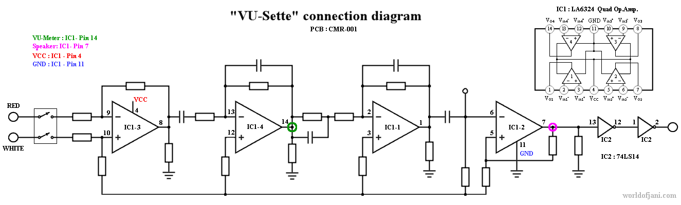
Circuit diagram for the VU-Sette.
I made a sketch with the information i had gathered. Connection points for “green” and “purple” can be found at the bottom of this page.
You might need to adjust the values to match the make and model of your VU-Meter/speaker. The speaker and the VU-Meter are independent of eachother. Either one can be left out if wanted.
Potentiometer R1 is for zero-adjusting the VU-Meter. The tape read-head signal and R1 must be adjusted to match. When the signal peaks, you want the VU-Meter be at the max position. You can use an original game, or a tape recorded with correct adjustment, to find the peak. Note that not all originals have a “good” recording signal to prevent duplicating.
The initial adjustment can be a bit tricky, but when it is done, you will only need to adjust the tape read-head when loading a tape.
I can think of some cases where you want to adjust the sensitivity further; for very bad/old tapes, or that the reference tape had a signal that was “too good” and you need to bring the level down a bit.
A Veroboard was used for the first build. I also needed to know much room there is inside the datasette for the pcb and VU-Meter. This version does not have the speaker.
PCB Layout
I ordered a few PCBs to test the concept. In retrospect, I would rather use solderpads for the speaker and for the VU-Meter. The VU-Meter would probably be able to hold the weight of the PCB and wouldn’t need any further mounting. The extra potentiometer snuck into the upper left corner can probably be left out, I wasn’t sure if there was a need for extra adjustment of the VU-Meter.
Assembly
A 22 mm hole for the VU-Meter was drilled 6 mm inwards from the junction.
Parts for the VU-Meter. The rightmost VU-Meter is from another batterytester i found on ebay. Both work with the VU-Sette, but the leftmost is easier to fit into the datasette.
VU-Meter with everything cluttered into the bottom left corner. 🙂
Fully assembled.
Finding the signal
The read-signal is amplified and filtered four times before leaving the datasette. Therefor the signal strength will be different depending on which stage you choose to tap the signal from. VU-Sette has been successfully implemented with the PCBs and connection points below. You might need to do some testing to find out which output stage is most suitable for your equipment. YMMW.
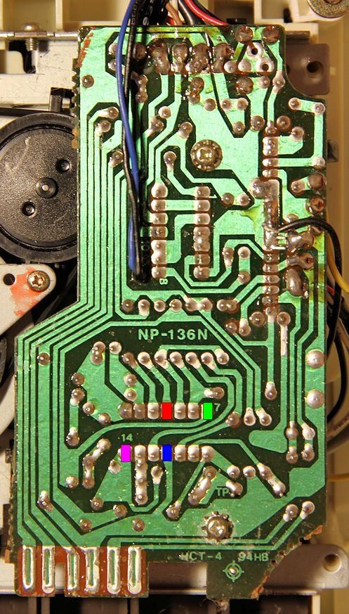
Datasette with one OP.Amp (PCB: 1530, 1531, NP-136H):