JaffyDOS d64 Copy v1.0 is for copying disks both way, from and to 1541/SD2IEC(d64). It includes a simple browser in which you can select a d64 image.
Press space to type in name of the D64 image (without extension) or use the D64 browser to select an existing D64 image. You can also press space in the browser to type in a new D64 image filename. Pressing F7 in the browser will dir the selected d64 file (SD2IEC only supports dir on a 35 track image).
JaffyDOS d64 Dump v1.0 is one way copy tool for “dumping” 1541 disks to SD2IEC(d64). This tool does not have a browser and will save the D64 image in the current SD2IEC path. It shows an detailed information on read-errors and will add the error information to the image if applicable. Press space to type in name of the D64 image (without extension). Program will loop and ask for next filename when finished reading an disk.
General Information
Full disk/d64 copy program only (no file copying possible).
Fast I/O. Copying a 35 track disk takes approximately 2 min with Jiffy/JaffyDOS and 4 min 30s with CBM kernal.
35 / 40 track support. Will be set automatically when selecting a .d64 image with the browser, otherwise configure it manually.
If you enter(by pressing space) a non-existing .d64 file/image, it will be created during the copy process.
An existing D64 file will be overwritten without any warning.
RUN/STOP can be used to exit to the main menu from the browser.
RESTORE key returns to main menu restarting the tool.
Default device number
You can “hack” the default source (green) and destination (red) devices to your preference by editing the two values above.
Thanks
Special thanks to Tom-Cat for testing and feedback !
RAMLink reproduction labels are offered by Corei64 and I decided to give it a go since my RAMLink label was worn. The color difference between the original and reproduction label is only due to the camera. Isopropyl alcohol and eraser was used to get the old sticker remains off.
Wanted: New GAL:s for my RAMLink, if anyone has successfully cloned them, please let me know.
Original RAMLink label.
Replacement label by Corei64, shipped promptly and very well packaged.
Final result, pleased with the result and quality of the label.
The 1541 has a built in +5V/+12V power supply which can be replaced with a switching mode powersupply, making it running much cooler, draw less power and weigh less. The 1541 capacitors are getting old and will likely need to be replaced soon.
Original powersupply components should be removed and +5V / +12V connected to respective output pin, or what used to be the output pin, of the regulators. I wanted to keep the heatsink as it helps holding the PCB up.
Warp Speed is a C64/C128 fastload (and tool) cartridge by Alien Technology Group who also made the (famous) V-MAX! protection/fastload system. They can be seen credited in titles as Defender of the Crown (among many others) and even made a game, Take Down Wrestling, and had close ties to Taito and Cinemaware(who also published the WarpSpeed cart).
ATG was started by Harald and Marty who hired in Joe occasionally to do some work for them.
All three of them did utilities for copying protected(!) software before starting up ATG. Marty and Joe worked for Prism Software and Harald did a fastloader and protection for a company named Basix.
I assume they realized there was a lack(or a need) of a good protection scheme thus starting up ATG and creating V-MAX!. There are many versions(or revisions) of V-MAX! and it can be seen evolving during the time on later games. Once a protection is out, the next game, or release needs to be altered so it wouldn’t be fully recognizable from the previous one.
Warp Speed has a DOS wedge with fast I/O routines for 1541/71/81 and a menu system for various tools such as sector editor, file/disk copier and a machine code monitor. The disk copier they included was deliberately chosen not to support copying protected software.
There are two versions of the Warp Speed ROM available, V1.0 and V2.0, and the manual mentions they crammed in 32K of code into 16K area by optimizing code over and over again.
Warp Speed ROM
The cartridge ROM is 16K with the following layout:
8000-9DFF
9E00-9FFF -> ROM at DE00-DFFF ; Load vectors and cartridge control
A000-BFFF
The cartridge is compatible with C64 and C128, there is a switch you need to flip to select mode. The C64 uses the BASIC cold start vectors at $A000 and for the C128 they check for the “CBM” ID-string at $8007-. The address and datalines are scrambled on the ROM, knowing their work with V-MAX! I’d guess they did that to protect the code with a benefit of simpler PCB layout.
OpenC64WarpSpeed https://github.com/SukkoPera/OpenC64WarpSpeed
Sukkopera has done a remake of the Warp Speed PCB. He did a version where the address and data lines have been unscrambled, using the sources below you can make your own customized Warp Speed cart ;).
Source Code
In 1999 the (partial) source code of V-MAX!, Take Down Wrestling and Warp Speed was released public by Marty (and Harald). The sources are in Merlin assembler format but I converted it to 64tass. You can download the sources and build an identical binary file as the (unscrambled) Warp Speed V2.0 ROM. The source code is very well documented and worth taking a look at.
All other downloads (manuals, original ROMs etc.) can be found at the OpenC64WarpSpeed page.
Thanks: Marty Franz, Joe Peters and Harald Seeley for Warp Speed. Sukkopera for the OpenC64WarpSpeed and giving me a notify of his project.
Terje(Abbyss) for sending me some Warp Speed PCBs!
Update:
Be sure to check out the blog post (and video!) by obliterator918 where he goes through the functions of the Warp Speed.
A very common issue on these drives are leaking capacitors causing damage on the motor control PCB. These should be replaced as soon as possible.
A few important notes on the way:
1. The screws holding the rotor(magnet) and especially the PCB screws are ridiculously tight, it’s almost as they are not loosening up at all. Make sure to have an exact size screwdriver and use correct amount of force to unscrew them, you don’t want to end up with destroyed screw heads.
2. There is a fragile flat cable on the underside, be aware of it before lifting up the PCB.
Remove the three screws and lift the rotor(magnet).
Remove the four screws holding the PCB marked with red circles and remove the spacers (mine had three of them).
Desolder the two connectors marked with red squares.
Close up of the cable in the lower left corner, be careful desoldering it.
Drive motor control PCB.
Position
Qty
Value
Dimension(mm)
C01/C02
2
22 uF 10V
h=7,5 d=5,2 r=2
C03/C17
2
4.7µF 25V
h=7,5 d=4,2 r=2
C05/C09
2
0.47µF 50V
h=7,2 d=4,2 r=2
C10
1
47µF 10V
h=7,7 d=6,5 r=2,5
C12
1
33µF 25V
h=7,7 d=6,5 r=3
C13/C14/C15 BIPOLAR
3
10µF 25V
h=11 d=5,2 r=2
Original capacitor values and sizes. h=height, d=diameter, r=lead spacing.
Position
QTY
Value
DigiKey #
Manufacturer
Manufacturer #
C01/C02
2
22 uF 16V
P15790CT-ND
Panasonic
EEA-GA1C220B
C03/C17
2
4.7µF 50V
P15838CT-ND
Panasonic
EEA-GA1H4R7B
C05/C09
2
0.47µF 50V
493-10466-1-ND
Nichicon
UMA1HR47MDD1TP
C10
1
47µF 10V
P14478-ND
Panasonic
EEA-GA1A470
C12
1
33µF 25V
P15805CT-ND
Panasonic
EEA-GA1E330H
C13/C14/C15 BIPOLAR
3
10µF 50V
P1280-ND
Panasonic
ECE-A1HN100U
Component list and manufacturer part numbers, some caps are rated higher than the original voltage value. There is limited space for the capacitors but the components above will fit. Capacitors C13/C14/C15 are bipolar.
Description
DigiKey #
Note
24 Position Connector SCSI Through Hole, Right Angle Solder
1024RFA-ND
ZoomFloppy
24 Position Plug Connector SCSI Through Hole Solder
1024PMA-ND
Part numbers for IEEE-488 Connectors also available from DigiKey.
SFD-1001 Head Resistance check.
Resistance RW1 or RW2 to CT : 37 ± 30% Ohms
Resistance ERASE to CT : 8.0 ± 30% Ohms
Information above from 8250LP SFD-1001 Disk Drive Technical Manual
RED-WHT
18
19,5
RED-BLK
36
37
RED-GRN
21
21,6
GRN-BLK
22
22
GRN-WHT
4
4,5
BLK-WHT
20
19.1
Measurements from the field on working drives for reference.
Mitch / ESI sent me a SFD-1001 disk with the sourcecode to Eagle Term II.
Since the disk was decades old, there was a risk it wouldn’t even be readable anymore. The disk density is 100 TPI meaning it couldn’t be read by just any drive, so the hunt for a SFD-1001 started. Fortunately I got held of one and connected my Zoomfloppy to it. The only thing it produced were a lot of intermittent faults. Thanks to forum64.de members, I built a IEEE-488(6522) interface and could conclude the drive was acting up. After replacing a couple chips and doing a full recap the drive started working.
I knew that this might be the only disk with the source code in existence, so I wanted to make sure to recover as much information as possible.
Before the first attempt to read the directory, I went native c64 to write a program which would save raw directory information into memory while displaying it on the screen.
Probably one of the last times the disk allowed for a directory to be read properly before giving up. All needed data was already recovered at this point.
After the first read, the drive started to have problems reading the directory. An ocular inspection revealed there was damage to the disk surface, this disk would not last for long.
To relief some stress on the directory track, I made another program to copy files from specific locations(TR/SE) with information on the D80/D82 diskformat and the data gathered earlier.
The process was slow, a lots of retries and a drive sounding like an old harvester. After 5 rounds of copying, the drive refused to load any files at all on the disk. I had gotten out different sizes on the same file, depending on how (un)successful the reading was.
Majority of the files were plain-text and ended with “.END” (assembler directive), which also was an indicator if the file had been fully copied. I could also verify, by reading the sources, if a file was cut in half and/or having incomplete blocks of code.
With 5 sets of files I could stitch together all data, except for one file: “IRQ.INC”.
IRQ.INC was missing 4 blocks of data.
;IRQ CONTROL

IRQON

 SEI

 LDA $0314

 STA IRQVEC

 LDA $0315

 STA IRQVEC+1

 LDA #IRQCDC

 STA $0315

 CLI

 RTS

IRQOFF

 SEI

 LDA IRQVEC

 STA $0314

 LDA IRQVEC+1

 STA $0315

 CLI

 RTS

;

IRQCDC

 LDA $DD01 ; PORT

 AND #%00010000 ; CARRIE
I reconstructed IRQ.INC by disassembling an earlier version of Eagle Term II and translated the v1.9 sourcecode into a modern cross compiler and downgraded(rewrote) it to the earlier version. That part of code was identical in both versions.
CBM DIRECT ASSEMBLER V080282 (C) 1982 BY COMMODORE BUSINESS MACHINES
After recreating IRQ.INC it was possible to build Eagle Term v1.9 using the original assembler.
THE SHAREWARE PLUS COMMODORE 64 & 128 BLOG sent me two 1541 Trackdisplay kits, one kit for Track and one for Sector. Normally I don’t modify original cases, but it was already cut up at a few places by the previous owner so I thought it’d be ok to cut up a hole in the front.
An overlay sticker is included in the package to cover up the hole which gives a really nice finish. Mine looks currently a bit rough since I added a piece of plastic in front of the display to dim the display and I need to finish up the installation with a 4-digit 7-segment display bezel, or make a custom sticker later on.
The kit is available for 1541/1541C/1541-II/1571/1581/C128D/C128DCR and requires some DIY. Everything is through-hole soldering and the manual covers the assembly in detail, you will not have any surprises or trouble assembling everything together. Soldering the The 7-segment display LED cables requires some patience though :).
This display supports displaying the current track AND/OR sector(or any memory location) which is an advantage compared to other solutions when studying loaders for example (nothing beats code reversing!). The display(s) will show “00” on intialization as the memorylocations are not yet populated, but its not a problem.
From the Manual: The Track Display is memory based, ie. the memory cells relevant for the respective drive types are monitored for change in real time. During write access to the memory cells, the hexadecimal data value of the memory cells is decoded and output via the 7-segment displays connected to the display drivers CD4511. The address selection and the decoding of one and / or several addresses are handled by an EPROM which has been programmed as a gate array. Theoretically, this design allows arbitrary memory cells to be represented by the SRAM of the floppy: track, sector, buffer pointer, status register – simply everything that is stored in the floppy RAM. Also, cascading several boards by stacking is possible, e.g. Track + Sector. For the sector display only a differently programmed EPROM is required.
You will get a nice package with all needed components and a manual.
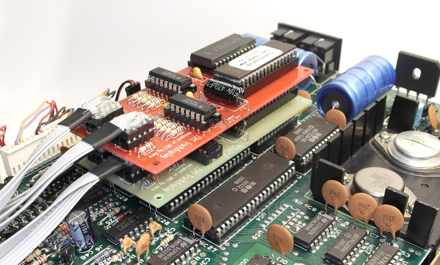
Populated PCB, 7-segment display connectors(IC sockets) are located on the rightmost part of the PCB. I installed a passthrough-socket for the RAM since the boards will be stacked. I also always install IC sockets as a routine. The sockets, however, added some height to the installation and caused me a bit of a problem later on.
The decimal points(DP) will be used to display which ROM is active and to show when drive is exchanging data with the computer. Wires and resistors for accessing the DP are present on the PCB.
Both ends of a 7-Segment-display cable. Shrinking tubes used on the wires to isolate and stabilize. The display and the socket are not 1 to 1 pin compatible so you need to cross a few wires (documented in the manual).
Some drives have large ceramic capacitors which can be replaced with smaller ones or, if space allows, bend them down a bit. They can be moved to the bottom side of the drive PCB in worst case.
Another approach is to add empty socket(s) to lift the PCB above the capacitors (picture is for illustrative purpose only).
Track AND sector trackdisplay PCB in place, stacking them became too high to fit under the lid, possibly because I added IC-sockets.
The kit allows for some DIY and there is lots of space in a 1541 drive. I connected the PCBs together with a ribbon cable and wedged the memory IC below the first board.
Installed a DolphinDOS under the Track/Sector display just out of curiosity. When resetting a DolphinDOS drive the display defaults to “77” or shows a “blank” display, probably to do with how memory is initialized. DolphinDOS mode runs too fast for the sectors to be readable on the display, not a big surprise though :).
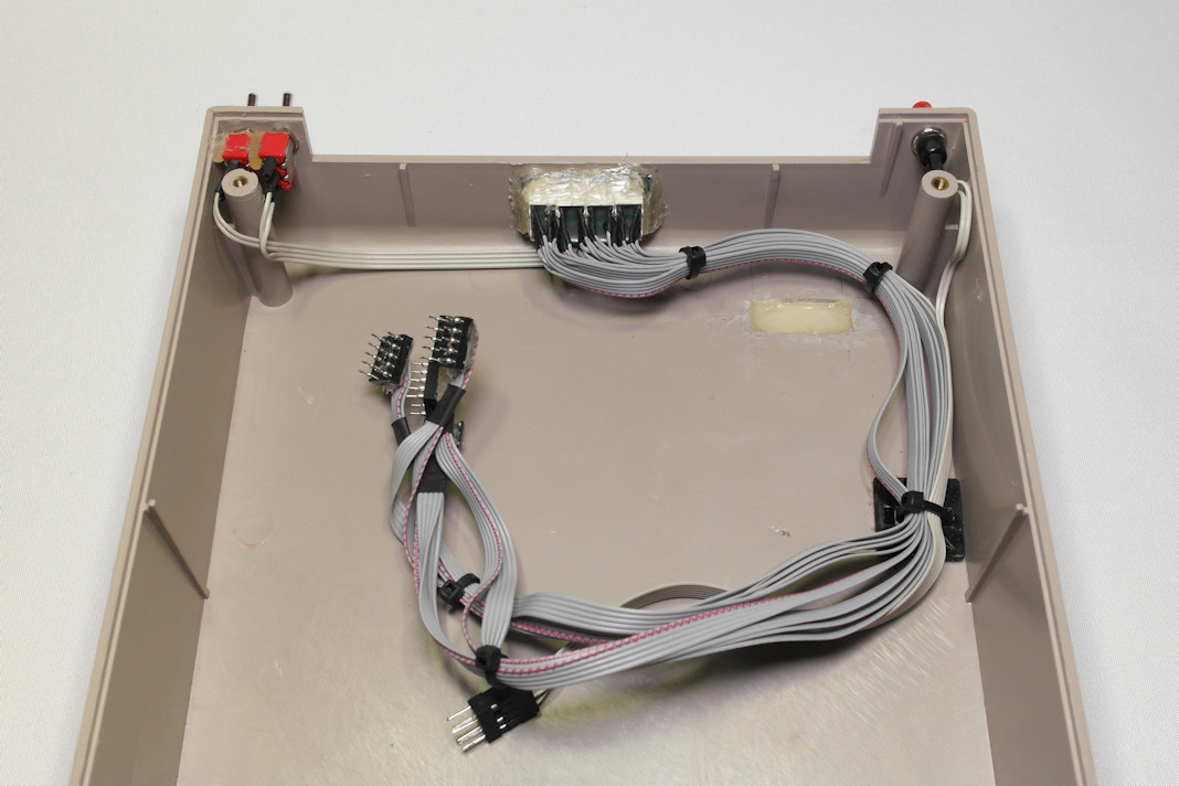
Inside the lid, cables and glue.
First part is fast formatting a disk, and second is loading a game where it switches to a fastloader after a while. The video does not quite do justice for the 7-segment LED display as it is more distinct in reality and no ghosting can be seen on the led segments.
The C128 was given a double-sized CHARROM which consists of the C128 characterset and the C64 characterset, both used in respective mode. The fonts differ in lowercase b, d, f, h, i, j, k, l, m, s, t, u, w and y (all C128 chars are equal to the plus/4 except for the m). Early C128 prototypes had only one font but there were some compatibility issues so they had to include the original font to be used in the C64 mode.
C64 characterset vs C128 characterset
National (SE/FI/DK/NO etc) models use the same font between C128 and C64 mode because the other bank is used to store the national characterset. You can switch between the charactersets using the CAPS LOCK-key. National models also have a 2764 ROM and a 2364 to 2764:ish adapter for U18, you can see the differences in an earlier post C128 vs C128d motherboard. The upper picture is a US C128 and the lower picture shows a SE/FI C128. Depending on the region, the CAPSLOCK-key can have different printings; “CAPS LOCK”(US), “ASCII/DIN”(DE), “CAPS LOCK ASCII/CC”(SE/FI) and possibly some more.
If the CHARROM(U18) needs replacement, the pinout is a 2364(8K) ROM. You can replace it with a 2764 using an “U18 adapter” (note that there is not much space under the RF-shield).
National modifications for C128
SE/FI machine. The brown wire connects jumper “J7” and CHARROM pin 23 (2764) allowing CHARROM bankswitching using the CAPS LOCK key.
Closeups of the modifications. CHARROM lifted out of the socket to see where the bankswitching wire is connected. The trace near C19 is cut and the wire connected to the rightmost pad of J7.
C128 CHARROM. SE/FI characterset with a factory U18 (2364-to-2764:ish) adapter.
A11 on a 2364 aligns with A12 on a 2764 and swapped to simplify the adapter. A12 on a 2364 aligns with /CE and therefor connected to GND. Swapping A11/A12 also means the order of the charactersets are different in the 2764 ROM.
TA11 = Translated Address Bus line 11, Shift+C=key (Upper/lowercase.)
CAPLK = Capslock key.
C128 Character ROM, U18, partnumbers
390059-01 US (2364)
315079-01 DE (2364)
315079-02 DE
325173-01 CH
325175-01 DK
325175-02 DK
325171-01 ES
325167-01 FR/BE/IT
325178-01 NO
325181-01 SE/FI
Dual/different fonts for 64 and 128
It is possible to replace the 2764 with a 27128 and modify the adapter by cutting at the red line and connect C64/C128 signal to 27128 pin 26/A13/yellow, allowing to have different fonts in C64 and C128 mode. First 8K would then be for the C64 mode and last 8K for the C128 mode.
Update 2024-04
Clarifications about the adapter and added dual font mod. Thanks to Per (RetroNynjah) for having good discussions about the subject! See his github for a reproduced adapter.
www.mediapalatset.com gave me a mystery cart which, after some investigation, turned out to be a floppyspeeder kernal cartridge. He also had a 1540 drive with matching speeder-ROM to accompany the the cart. Thanks ! 🙂
The internal Kernal-ROM can be replaced with an external Kernal-ROM cartridge. This cartridge design is a different one than the standard cartridges mentioned at Making a C64 Cartridge and should not be mixed up. The only common thing is area $E000-$FFFF, which is used by Kernal-ROM and Ultimax-mode (RAM at $E000-$FFFF needs also to be taken into consideration).
You can not use plain Ultimax-mode to create an Kernal-ROM cartridge since Ultimax will bank out all memory between $1000-$7FFF and $A000-$CFFF making it rather unusable. A way to enter Ultimax-mode only when accessing (Kernal-ROM) area $E000-FFFF is needed.
To determine if adressing $E000-$FFFF should be ROM or RAM is done by setting HIRAM bit in $01 CPU I/O-register. Having an external ROM at $E000-$FFFF in the cartridgeport causes problems since the cartridgeport HIRAM-signal is used for accessing the BASIC-ROM at $A000-$BFFF. There is no equivivalent HIRAM-signal for $E000-$FFFF in the cartridgeport.
The simple solution is having some extra logic and attach a wire from the cartridge to the HIRAM-signal inside the computer, therefore kernal replacement carts most often come with a cable and a clip for this purpose. An example of this is the V-DOS / EXOS V3 (REX9805) cartridge. You can leave the wire disconnected but access to RAM at $E000-FFFF is not available which limits the functionality a lot (unless running plain basic).
EasyFlash3 and 1541Ultimate use a more elegant solution without a need of an extra wire, Skoe has written an excellent document in the subject: How to build a real Kernal Cartridge.
Turbo DOS V3
The cartridge had a sticker on it saying “Turbo DOS V3” (Drive returns “Turbo dos v3”, kernal startup-message says “Turbo System v3”). The cart also had a reset-button and a switch to be able to change eprom banks for (inter)national kernal. The wire was connected to the solder dot left of the 74LS30 IC. Delikatess-data was a shop located in Gothenburg, also selling Dolphin DOS at the time. I desoldered all components and scanned the PCB for documentation purposes.
HIRAM-Signal and the wire
The cartridge needs a wire connected to the HIRAM-signal inside the computer which is located at pin 28 on the CPU, you can study the schematics for more convenient locations of the HIRAM-signal.
Clip connected to pin 28 on the CPU (C64E / Assy 250469).
OpenC64KernalCart by Sukkopera
I was in contact with Sukkopera asking if he interested in doing a PCB for the kernal cartridge. He did a great job and refined the design. You can now have 8 different kernals on the external cartridge selectable by jumpers.
OpenC64KernalCart holding 8 different kernals. The HIRAM-signal should be connected to the yellow pin-header.